Garmin-Asus Garminfone Hard Reset Procedures


Here's how to Reset the Garmin-Asus Garminfone  to Factory Default Settings      

Please note: the following process will restore your device to the default state settings and erase all of the data and downloaded applications stored on your Garmin-Asus Garminfone. Please ensure that you back up all required data before you reset the device.    

First, try this:

   1. From the main home screen, tap menu
   2. Select Settings
   3. Press the menu key, then Select Master clear
   4. Enter your password if prompted, then Select Yes to confirm

If the device is frozen and the above procedure does'nt work, try the following method below.

   1. Turn the power off. If your Garmin-Asus Garminfone is frozen, pull the battery out and reinsert it back
         again
   2. Hold the Left D-pad button
   3. Press and hold the Power button until the device turns on
   4. Follow the on-screen instructions to restore the phone


All of your data stored from the Garmin-Asus Garminfone including third-party applications will be deleted . Once the software reset is complete, the phone will then reboot to its factory fresh  default state settings.

Dell Streak Hard Reset procedures

Dell Streak Tablet Android Phone (AT&T)

Here's how to Reset the Dell Streak  to Factory Default Settings       

Note: The following steps will restore your device to the default state and erase all data and downloaded applications stored on it. Ensure that you back up all required data before you reset the device.    

First, try this:

   1. From the main home screen, tap menu
   2. Select Settings, then Privacy
   3. Select Factory data reset
   4. Select Reset device
   5. Select Erase everything

If your device is frozen and the above doesn't work try this,
   1. Press and hold the Power button  and then touch the Power off option on the screen to turn off the device.

   2. Simultaneously press and hold the volume up button  and volume down  button.

   3. Without releasing the volume buttons, press and hold the power button until the device displays the configuration screen.

   4. Press the volume buttons to move the highlight bar on the screen to the Factory Reset option.

   5. Touch the Camera button  to start the reset process.

   6. Wait for the device to reboot.

All of your data stored from the Dell Streak including third-party applications will be deleted . Once the software reset is complete, the phone will then reboot to its factory fresh  default state settings.

Understanding WLAN and GPS Circuit on Smart Phones

Additional features such as Bluetooth, WLAN and GPS on Smart phones become more popular in the market. As a techie you also need to figure out how this circuit works in order for you to catch up a new evolving designed on mobile  phones.

These additional features is packed into an IC component module in a circuit, and this kind of
of circuit are associated with a master clock which typically a external clock crystal oscillator.
With the master clock the data transmitted or received  is modulated to a proper certain frequency.

Here's how simply tells us how the circuit works on smart phones.

The WLAN circuit
 Wireless Local Area Network (WLAN) links two or more devices using some wireless distribution method (typically spread-spectrum or OFDM  radio), and usually providing a connection through an access point to the wider internet. This gives users the mobility to move around within a local coverage area and still be connected to the network.

A typical block diagram below shows bluetooth wlan circuit, this block diagram will tell us how the clock oscillator feeds desired frequency to the WLAN module. The Wlan is associated is with the bluetooth transceiver circuit to send receive the data from the Wlan module to register it to the application processor.
In this diagram shows that the WLAN module also needs the RF clock to make it work, this RF clock comes from the RF circuit. In other designed aVoltage Controlled Temperature Compensated Crystal Oscillator(VCTXO) is used as an external clock generator.

Typical block diagram of Bluetooth WLAN circuit
Bluetooth Wlan circuit block diagram

The GPS Circuit
The Global Positioning System (GPS) is a space-based global navigation satellite system that provides reliable location  and time information in all weather and at all times and anywhere on or near the Earth when and where there is an unobstructed line of sight to four or more GPS satellites.The GPS (global positioning system) circuit comes with a GPS module this is packed into chip, a GPS RX filter, GPS clock crystal oscillator and a GPS antenna.
In this block diagram the GPS module is being feed with different RF clock data signal which also comes from the RF circuit.
Typical block diagram of bluetooth with WLAN and GPS circuit
bluetooth wlan gps circuit lock diagram

The components layout of Bluetooth, WLAN and GPS circuit on a PCB board.
This shows an example of the bluetooth circuit associated with WLAN and GPS circuit mounted on PCB board.
gps wlan circuit components
You'll figure out that all circuit components such as the ic oscillator, bluetooth chip, wlan chip and gps chip is mounted all together with each corresponding connections. The RF clock is  located on the RF circuit section which is comes from the RF chip.


And here's an schematic diagram of WLAN and GPS circuit, for knowing how the circuit components connected with each corresponding components.

This  is only a simple explanation how does the circuit works, the main key for this lesson is how to figure out and used this tutorial in troubleshooting and repairing GPS and WLAN problem and failures on a particular mobile phone devices, that we are going to tackle it here and so on...

Understanding about bluetooth circuit in mobile phones, a key to fix bluetooth problem issues

We already know that Bluetooth is an open wireless device technology standard for exchanging data over short distances from fixed and mobile devices(using short wavelength radio transmissions), creating personal area networks (PANs) with high levels of security.The Bluetooth baseband protocol is a combination of circuit and packet switching. Slots can be reserved for synchronous packets. Each packet is transmitted in a different hop frequency. A packet nominally covers a single slot, but can be extended to cover up to five slots. Bluetooth can support an asynchronous data channel, up to three simultaneous synchronous voice channels, or a channel, which simultaneously supports asynchronous data and synchronous voice.
and that's how it simply  works.

Since we are talking about mobile phones here, it is much more really great to know how really bluetooth circuit works on cell phones circuit? Isn't it nice to know, so that we can easily managed how to fix it since it is our main reason in this tutorials by learning how to repair damaged cell phone devices.
In mobile phones Bluetooth problems also occurs when the bluetooth circuit is damaged, Some new cell phone techie find it hard to fix bluetooth for not knowing how the circuit works.

Okay, lets tackle  it for a while in just very simple explanation so that all of those without any background in electronics  might can catch up too, and then we can use it in our everyday job on GSM field.

Figure the bluetooth circuit block diagram below for it shows how the Bluetooth Circuit works according to each corresponding parts or components that is being connected to it.

mobile phone bluetooth circuit block diagram
Typical block diagram of a Bluetooth Circuit
The bluetooth transceiver module is packed into chip or IC (integrated circuit), this chip needs a certain power supply to make it work. All the data that has been transmit (send) and receive from the bluetooth antenna and bluetooth RF (radio frequency) transceiver  is feeds in for receiving and feeds out when sending to the application processor (cpu IC). There is an RF clock which comes from the RF circuit section is also feeds into it, that certain RF - Radio frequency is also needed by the bluetooth module to make it fully functional.

Since all those certain parts on bluetooth circuit were packed only into chips. A way to truly understand how does the circuit connect with each other from each certain components is by reading the circuit schematic diagram to locate this certain components parts on the main PCB board so that we can be able to check, trace and fix when a bluetooh failure happens. here's an example of the bluetooth schematic diagram and figure out how each components connect with other. In this method you can easily identify where that certain parts connected from one another.  See here:


And here's an example of the Bluetooth circuit  layout of components on a PCB board.
You'll notice that all of the bluetooth components is mounted in one section and near to each other. Some important spots is being labeled for quick troubleshooting guide. Like this picture below, the voltage supply and the RF clock are being labeled for quick check up and test procedures.
The key reason with this is that when it comes fixing bluetooth problem issues is to check the supply voltage and the RF clock signal first before trying to check , test, replace any other corresponding components being connected within the whole bluetooth circuit.

For any further deeper questions just post it unto the chat box page.

Solving Camera Flash/Torch LED failure on Nokia 5800

A camera flash LED is high power super bright LED and it is driven by a high power compact Flash/Torch LED driver IC. This LED driver chip controls the LED current and improve flash brightness and picture quality in dimly lit environments.
Flash LED failed due to overload, short and open circuits, wet damaged, accidentally dropped and any other means of related causes.
Nokia 5800 xpressmusic camera flash light ways
Fixing the camera Flash LED failure is quite not too difficult on Nokia 5800 , its because the flash LED components were all mounted and located in an isolated part of the main PCB board.

Hints for repair:
* check the smd fuse and coils continuity. these is where the supply voltage feeds across from the cell
      phone's battery.
* Remove the Flash/Torch LED driver IC, trace each of terminals connection to a corresponding  
     component  parts.
* Replace the Flash/Torch LED driver IC.

Here's the datasheet of Camera Flash LED driver IC for a deeper knowledge of how this IC component works.

A guide to fix Nokia 5800, Camera Hardware failure

This repair guide shows the Nokia 5800 Xpressmusic main camera circuits components that may possibly damaged and result to camera hardware failure.
Some of camera hardware problems such as, camera on standby mode, a blank or black display appears when the camera is open.
This solution can be used for tracing the line paths and for easy locating the camera circuit components that is connected within the camera circuit. however; this repair guide can only be used if the main camera module already been check, test or already  installed a new replacement camera module but the problem still exists.

Nokia 5800 xpressmusic camera repair solution
nokia 5800 camera ways
In most common problems that may occurs in fixing camera problems is that the supply voltage is loss or being cut and result to such problem issues, this may happen if the unit is damaged by a liquid or water damaged. But not totally happens as always like that, it also comes from any basis, like interrupted firmware, the camera module contact pads on the holder were corroded and caused an interference on the  data signals.

Camera failure repair hints:
Checking the firmware and replacing a  new camera module replacement may the first step to fix camera failures, the next thing you could do next is by checking  the desired supply voltage that feeds to the camera module before trying to touch any other components within the circuit. 

In this circuit there are three supply voltage that feeds to the camera module.
1. Vbat - a supply voltage from the cell phones battery 3.7  DC voltage
2. Vcam_1.8 - camera voltage 1.8 DC voltage
3. Vcam_2.8 - camera voltage 2.8 DC voltage
If one of these three voltages is missing the camera will not be able to function.
The Vcam or camera supply voltages is feeds from a DC to DC converter SMD IC, this smd ic converts the battery voltage  to a desired certain voltages such us 1.8 volts and 2.8 volts.
You may easily  check each of these voltages by locating a certain components  parts like filter coils (power inductors) and smt capacitors, in which this particular voltage flow across to it.

Make a continuity check on all data lines paths from a particular components to each of the camera module terminal pins. Next have all corresponding smd components be check or replace like the filter coil, resistors and capacitors.
Reworking or reballing the solder balls of the camera chip or replacing it may possibly fix, if all of the above does not solve the problem.

Nokia 5800 LCD Display Backlight LED's Failure - repair solution guide

Here's  the solution on how to repair Nokia 5800 Xpressmusic LCD backlights  failure that result to a dark, black screen display.This solution simply show the line paths of each particular components of where it is being connected in the main PCB board circuit.

Nokia 5800 LCD Display Backlights LED's repair

 The Nokia 5800 Xpressmusic used an LED driver IC same as other Nokia mobile phones, this IC chip drive and control the current and voltage to LCD backlight LED.

Repair hints, refer to the picture above:
1. check and test the LCD backlight LED's, you can do it by setting the Multimeter to X1  just refer to the pictures above for the pin configuration.  The positive (cathode) and the negative(anode) is indicated on the LCD pin connector. If the backlight LED's wont light up, a new replacement LCD is necessary.
1. Check the coils for continuity and resistors resistance value, replace if found busted or damaged. A very low resistance resistor can be easily damaged when a short circuit happens. Short circuit happens when the device is damaged by a liquid or so called water damaged handsets.
2. Check the line paths  between each components, you may start from the pin connectors then between particular component parts.
3. Check the Vbat voltage across the filter coil. this voltage is the positive voltage of the battery, you can check it also by doing continuity check from the cell phone battery positive terminal to the coil.
4. Remove the LED driver IC, check both of each solder ball line paths to where it is being connected to a particular components. If all lines were okay find a new LED driver IC replacement and replace it.

Understanding how RF circuit Works on Cell Phones

mobile phone rf circuit block diagram

In cell phone repair it is very helpful to understand how the RF circuits works , for this is a big help when
troubleshooting No signal problem issues.
RF stands for radio frequency , this frequency is used to  transmit and receive the data signals from a mobile phone.

Here's a brief explanation on how does RF circuit works on mobile phones.
This is for GSM RF circuit only, although the WCDMA circuit and WI-FI circuit have similarity on this but I will try to explain both of it hereafter.

See the block diagram below. Observe how the frequency data signal feeds from a certain parts of an RF circuit design.
A breakdown or failure of each certain part will result to signal loss and the capability to generate, amplify, control , process, send and receive the desired radio frequency during transmission process. 
cell phone RF circuit

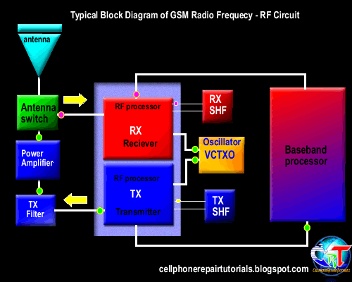
In mobile phones transmission there are two types of operation took place, the receiving operation and the transmitting operation.
In normal mode, RX part is always active in receiving operation the antenna switch is always open its gateway through to the RX circuit, It is always ready to receive and intercepts the radio waves and wait for the desired frequency signal to catch up.
During transmission like making a call or sending a text message the antenna switch will close the gateway of the RX and open the gateway of the TX in order not to interfere the data signal during transmission.
All data that has been receive and before to transmit or send, all this data signals are feeds to the baseband processor.

An explanation  of an RF Circuit Parts and what possible problems if a certain part is damaged.

RF Receiver - ( RX radio receiver )
The rf receiver are called RX, this circuit is design to receives, and process the data signals from the airwaves during transmission process. A failure of this circuit will result to unable to receive data signal during transmission.

RF Transmitter  - ( TX radio transmitter )
the rf transmitter are called TX which is the one that process, amplify  the data signals from a mobile phone . 
Once failed to initiate  a failure to transmit radio frequency signal, this will result to unable to send data signal during transmission. .

Power amplifier -  RF amplifier
The power amplifier is used to amplify, boost up the radio frequency signal before it feeds to the antenna before it thrown over the air waves during transmission. If damaged will result to signal loss, a dropping signal indication on the display.

The Antenna is used to intercepts and thrown the radio radio frequency in the air  during transmission
When electricity is "thrown" into the metal of an antenna, the metal reacts to the electricity at an atomic level in the form of a wave.
if damaged or due to a corroded terminal pads, will indicate and show a poor signal or low level frequency signal.

Antenna switch
The antenna switch is used as a gateway that controls and manage the frequency to pass through, it switch the RX frequency signal and TX frequency signal during transmission process. literally  the antenna is the signal catcher and likewise the signal thrower. If damaged the gateway to the antenna will be closed and result to network signal indication. 

Crystal oscillator
Generates a desired frequency that feeds to the RX and TX circuits. In mobile phones a Voltage controlled Oscillator (VCO) and Voltage Controlled Temperature Compensated Crystal Oscillator (VCTXO) is used in rf circuit.
If damaged the RX and TX will not work and the RF cicuit is at full failure.

SAW filter
Surface Acoustic Wave filter used as an rf synthesizer to purify  a desired level of frequency. If damaged result also to no network signal indication.

An example of the  RF circuit components layout on a PCB board.
The rf circuit components are often covered with shielding metal case unlike the baseband processor parts which is oftentimes not. This is because frequency is very vulnerable with unwanted radio waves interference and destroys data signals. Using the shielding metal will minimize the radio waves interference.

For further questions just post a message on the shout box page.

Nokia 5730 SIM card assembly connection - Test spots for troubleshooting

The SIM Card circuit of Nokia 5730 Xpressmusic, this guide can be used to troubleshoot and repair Insert SIM Card problem when occurs. The SIM card connection is rarely the same as of some any Nokia mobile phones handsets, The 5730 does not have a SIM filter IC unlike others do have.

The SIM data, clock and reset signals is feeds directly from the PMIC (power ic) located at the right bottom of the main pcb board. Each signals used bypass capacitors to ground lines which is mounted behind the SIM card connector socket. The SIM supply voltage (VSIM) used a filter coil mounted located near at the SIM socket.


You can trace each individual lines paths during hardware repair. You may start from checking the supply voltage first by checking the filter coil and the line paths across to it from the VSIM capacitor near to the PMIC (power ic).
Check the Data, Clock and Reset line paths through to each capacitors.
For further deeper troubleshooting check it here and learn how the SIM circuit works.

Solve Nokia 5730 Xpresmusic Restart Problem When Charging

If your Nokia 5730 xpressmusic often restart when charging or a charger is plug-in it always restart. Here's a simple solution  to fix the restart issue, all what you have to do is update your phone firmware to the latest versions..

Instructions to make the update
1) Download and Install "Nokia PC Suite" on your PC.
2) Download and Install "Nokia Software Updater" on your PC.
3) Back up phone memory on the 8GB SD Card.
4) Remove the 8GB SD Card from the phone.
5) Make sure that the phone is fully charged.
6) Connect the phone to computer via USB Cable.
7) Start "Nokia Software Updater".
8) Follow the steps.

You can also used this method by using Nokia Ovi-Suite
and then update it to version 200.12.87  or higher and latest firmware versions.


For mobile technicians tips. Flash the Phone to latest and higher versions, this problem cause by a corrupted firmware. If the software update does not solve the issue, See here for which components needs to be check or replace. This problem occurs because the designed of  5730 Xpressmusic  is not the same to other nokia mobile phone models circuit designs. The power ON/OFF switch is being connected with an IC that is also combined with a charging switching mode. If the said IC is damaged the charging data signal will  trigger the power ONX of the PMIC (power IC) that will result to restart the phone or powering it ON and OFF again.

Nokia 5730 Xpressmusic LCD LED Backlight Failure Solution

Here's the repair guide solution to repair Nokia 5730 xpressmusic LCD LED backlight problem, a failure when the LED backlight failed to light up that result and turns the display into a dark, black or blank screen display.
This solution may only work and can be applied if the LCD and flex cable is properly check, test or by way of replacing it already but the problem still exists.

In Nokia 5730 the LCD LED backlight is driven and controlled by an SMD LED driver IC, this chip is located or mounted just located near at the bottom left of the main PCB board. The chips Power supply voltage which feeds directly from the cell phone's battery (VBAT) which is approximately 3.7 volts DC. This voltage is being filtered by a large Filter coil, You may check the filter coil first, then trace the line paths on it.
You may also then remove the LED driver IC and trace all corresponding lines from the chips ball bumps through to the flex cable pin connector, which is in pin number 47 and pin number 50.
Just follow the picture guide above to determine each of its line being connected. Replace the LED Driver SMD IC if all line paths are working fine.

Samsung Moment SPH-M900 Hard Reset - procedure

 Samsung Moment SPH-M900 Hard Reset, restore to factory default settings procedures.

Note: Please make sure to do a back up of your data stored on your Samsung Moment, this process will delete all data stored on your device.
Spring Flowers Snap On Protector Case for Samsung Moment M900 Sprint
To Restore to factory settings

   1. From the application menu, Select Settings
   2. select SD Card & Phone Storage
   3. Select Factory data reset
   4. Select Reset phone
   5. Enter your password if required, then Select Yes to confirm

To do Hard reset  if your phone is frozen:

   1. Turn the power off. If your Samsung Moment is frozen, pull the battery out and put it back again
   2. Hold the Volume Down button, Call and End until "Samsung" appears on the screen along with a menu
   3. Select Master reset device
   4. When the phone is done erasing, choose the option to reboot

Once the Samsung Moment reboot it returns back to factory-fresh default state settings.

Nokia 5730 Xpressmusic keypad LED backlight problem - repair solution

This repair solution can be used  to solve Keypad LED backlights problem on Nokia 5730 xpressmusic.
In Nokia 5730 there are two LED driver IC that controls the voltage and current to the keypads LED backlight. The first LED driver on the left side controls and managed the four LED's on the keypads while the other one the right side holds and control only two LED's.

nokia 5730 keypad LED backlight solution
The repair solution picture above may help to easily determine which LED driver IC seems to be damaged by identifying which LED driver holds and control that particular LED backlight that does not light up.
Check the LED backlight first before doing anything further.
If the four LED's on left is not working, you may check or replace the left side LED driver IC, same also when the two LED's on the right stop working you may check also the LED driver IC on the right side.
Just analyze and observe carefully how the LED backlight driver IC works.
Check the connection of the LED driver IC's ball terminals, including which signal or which particular line it is being connected with.Check the power supply voltage, which is connected direct to the battery VBAT voltage range range 3.7 volts. Trace and check all the lines, then apply jumper wire when found cut or open.

Nokia 5730 Xpressmusic Earpiece Speaker - No Audio Sound Solution

Here's the solution that can be used to solve the earpiece speaker problem on Nokia 5730 Xpressmusic .
As the earpiece speaker assembly is mounted and connected on a flex cable ribbon, so in this kind of design, the audio signal may loss if the flex cable is being damaged or cut and this will result to no audio sound can be heard over the earpiece speaker.  On the picture repair guide below you can trace the earpiece speaker line paths across the flex cable before trying to replace it with a new one; but make sure to test and check the earpiece speaker first before doing anything further.
Now, if the speaker and the flex cable seems both working fine, you may then proceed to check the line filter coils as indicated on the picture guide.

Click the images to view and download the large one
Nokia 5730 Earpiece speaker repair solution

Replace it with similar value, you may find it on other non working PCB board of other  Nokia mobile phone old model. Check the line paths across the pin connector to the filter coil, apply a a tiniest magnetic wire jumper if found open or cut.
If all of the above does not fix the problem, the last part will need extra precaution and expertise or you may end up killing the phone.
But this will only  happen occasionally and so rarely and may occurs if the phone's history is damaged by a liquid (water damaged) or being accidentally heavily dropped.

You may  proceed to rework, re-ball, clean the PMIC (Power IC),  the earpiece audio signal is connected to the terminal (C2- positive and D3- negative) of the PMIC. While the PMIC is being remove make sure to trace this lines through to the filter coils from those earpiece audio ball bumps from the PMIC before mounting it back to the main PCB board.

solutions to solve blackberry series hardware problems - repair manuals

Download solutions for Blackberry series hardware problems; this solutions were tried and tested to solve of some blackberry known hardware problem issues.
These repair guides are covered the following Blackberry Mobile Handset devices: 7100 series, Curve 8310, Curve 8320, Curve 8700, Curve 8900, Bold 9000, Bold 9700,
All blackberry hardware solutions

name of the archive download
All Blackberry  Curve 8310, Black Curve 8320  repair solution for the following problems -
Keypads malfunction, microphone failure, Scroll keys malfunction, Insert Sim card problem,  Camera hardware Failure, Not charging problem, No ringtone/ buzzer problem

download
Blackberry 8700 Dead set / shorted repair solution download
Blackberry Curve 8900 No network signal problem repair solution download
Blackberry Curve 8900  ringer / buzzer solution - this solution may help to fix No ringtone sound on the device download
Blackberry Bold 9000 No power / Dead Set repair solution download
Blackberry Bold 9000 USB failure solution - Unable to read the device on USB port download
  Blackberry Bold 9700 Camera Flash Failure solution - unable to light the camera flash light download
Blackberry Bold 9700 White Screen solution - White screen of death WSOD repair download
All Blackberry Hardware solution collection vol. 1 - blackberry repair picture packed download
All Blackberry Hardware solution collection vol. 2 - blackberry repair picture packed download

Nokia 5310 XpressMusic Display Problem (NO Display) Repair Solution

Here's how to repair Nokia 5310 XpressMusic Display problems.
This solution may help to fix the follwing Display problem related issues on Nokia 5730 like,

Garbled display
Saturated display
Distorted display
White screen display (white screen of death -WSOD)
Blue screen display
Blank or black screen (No display)


Troubleshooting this kind of problem seems to be easy, you can start by checking first the LCD pin connector if it is free from dust, dirt or corrosion. A corroded pin connector also interrupts the display data signal that is being feed to the LCD screen display. Then check all resistors just located right top of the PCB board layout. These resistors valued  33 Ohms each of it.

nokia 5310 display problem repair solution

If found busted or damaged you can temporarily short the resistor's terminal by applying a little bit solder on it, before replacing a new one, in this manner you can easily identify if the line path of that particular resistor is okay, then assemble back the LCD and power on the handset, and check if the display is seems to be working fine. If its already working good, then remove the solder on the resistor and replace a new one with the same value. Do Not leave it shorted or it may end up other and much more harder to fix problem.
nokia 5310 LCD display ways

You can also do check the line paths of each particular resistor way through to the LCD pin connector (B to B connector). Each line colors correspond to  the location or the number of the pin which is connected to a particular resistor. You may check if that line is okay. (multi-meter continuity check), Then apply a tiniest magnetic wire jumper if found a line that is being cut or open.

Nokia 5730 XpressMusic LCD display problem - hardware repair solutions

This solution works on Nokia 5730 XpressMusic display  problems like garbled, white screen, blue screen that is related to hardware failures. This solution may only apply if the flash firmware is already been done and seems to be okay and the flex cable assembly has been completely check or  replace but the problem still exists.
In Nokia 5730 XpressMusic the LCD display data signal used two EMI-filter IC and a display data controller IC which is feeds from the application processor (CPU IC). see the repair guide picture layout.
One of the EMI filter marked with number two is also used for the keypad interface filtering designed. This IC shared the three input and output lines for the display data signal filtering.
5730 display problem repair solution

You can check this tiny chips using the guide below before replacing them with a new one; the first one is approximately range 0 -100 ohms  resistance value and the second one is up to 70 ohms per each input and output lines.
If both display EMI- filter IC already check or replace, and the problem still exists, you may then proceed to check and rework or replace the display data controller IC which is marked with number 3.
The last part which is heavily needs extra expertise to work with is the application processor if all of the above doesn't solve the problem.
By reworking or replacing the application processor is the last part that may solve the problem. You need to re-flash or re-build the firmware after you have replace it.