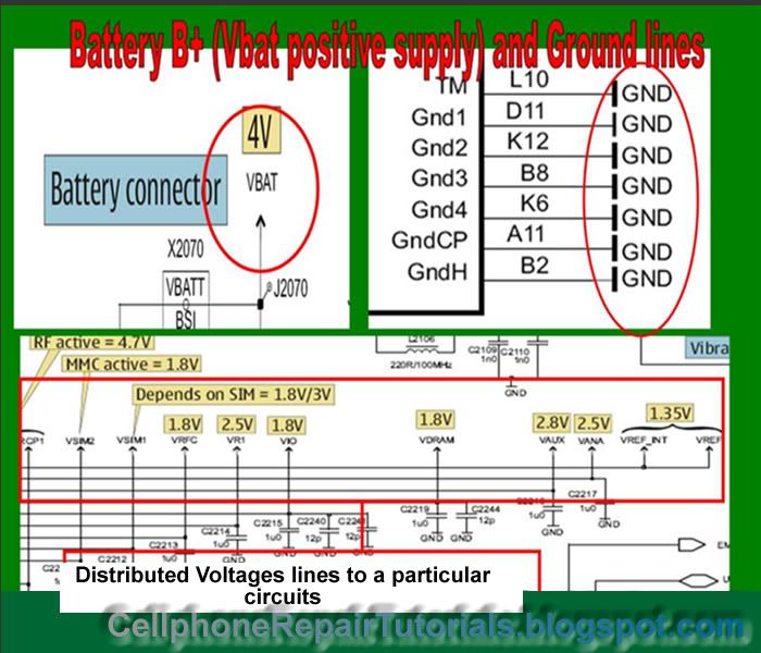
Lines Symbols on schematic Diagram have different specifications.The lines is the path way of every technician for tracing connections from one component to another components or circuits.
Every lines is being specified for a certain purposed, to let the troubleshooter know of what particular source flows on it, like, positive voltages, negative or ground lines, currents, frequency signals, logic digital signals, clock data signals,etc.
In this lesson we are going to take a brief knowledge on how to identify each specified lines for this is so important when it comes to hardware troubleshooting methods.

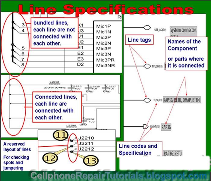
Lines Tags and Specifications
Line Specifications is also the basis on how and where that certain components connects across to another components. In this method, finding and tracing in between line to to line is easy for troubleshooter. This is also helps to identify which particular circuits accompanied by a certain components.
Bundled lines- Its a line composed of many lines being combined into one thick line symbol to indicate that the line is composed of assorted line areas across to it.
Line codes - A label used to identify a line continuation from circuits to circuits.

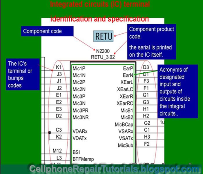
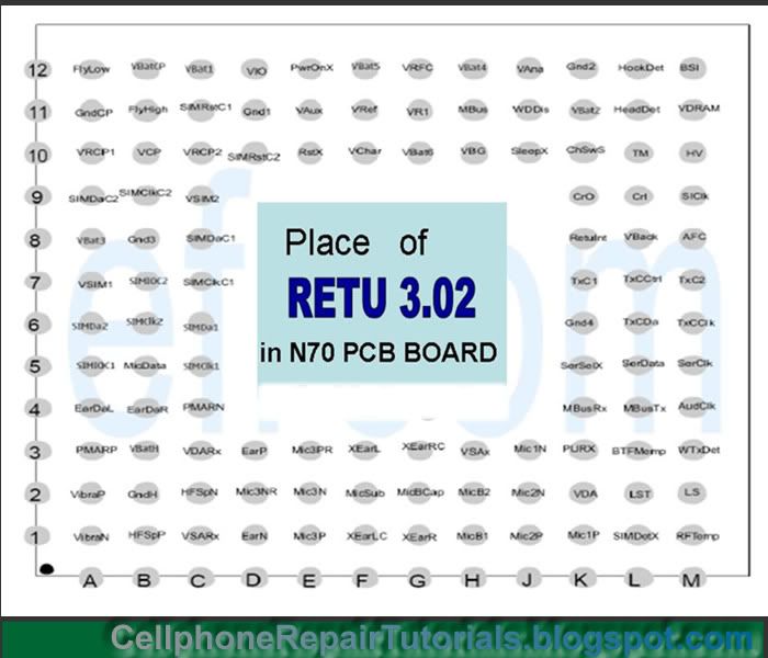
Integrated Chips also coded with letter and number combination. The line codes specify the bumps or terminal pattern of the chips package.

The line codes is used to determine each bumps or terminal took place on the main chips terminal patterns

A power IC RETU of Nokia Handsets


0 comments:
Post a Comment