Showing posts with label Nokia 5800 Xpressmusic Repair Guides. Show all posts

Solving Camera Flash/Torch LED failure on Nokia 5800

A camera flash LED is high power super bright LED and it is driven by a high power compact Flash/Torch LED driver IC. This LED driver chip controls the LED current and improve flash brightness and picture quality in dimly lit environments.
Flash LED failed due to overload, short and open circuits, wet damaged, accidentally dropped and any other means of related causes.
Nokia 5800 xpressmusic camera flash light ways
Fixing the camera Flash LED failure is quite not too difficult on Nokia 5800 , its because the flash LED components were all mounted and located in an isolated part of the main PCB board.

Hints for repair:
* check the smd fuse and coils continuity. these is where the supply voltage feeds across from the cell
      phone's battery.
* Remove the Flash/Torch LED driver IC, trace each of terminals connection to a corresponding  
     component  parts.
* Replace the Flash/Torch LED driver IC.

Here's the datasheet of Camera Flash LED driver IC for a deeper knowledge of how this IC component works.

A guide to fix Nokia 5800, Camera Hardware failure

This repair guide shows the Nokia 5800 Xpressmusic main camera circuits components that may possibly damaged and result to camera hardware failure.
Some of camera hardware problems such as, camera on standby mode, a blank or black display appears when the camera is open.
This solution can be used for tracing the line paths and for easy locating the camera circuit components that is connected within the camera circuit. however; this repair guide can only be used if the main camera module already been check, test or already  installed a new replacement camera module but the problem still exists.

Nokia 5800 xpressmusic camera repair solution
nokia 5800 camera ways
In most common problems that may occurs in fixing camera problems is that the supply voltage is loss or being cut and result to such problem issues, this may happen if the unit is damaged by a liquid or water damaged. But not totally happens as always like that, it also comes from any basis, like interrupted firmware, the camera module contact pads on the holder were corroded and caused an interference on the  data signals.

Camera failure repair hints:
Checking the firmware and replacing a  new camera module replacement may the first step to fix camera failures, the next thing you could do next is by checking  the desired supply voltage that feeds to the camera module before trying to touch any other components within the circuit. 

In this circuit there are three supply voltage that feeds to the camera module.
1. Vbat - a supply voltage from the cell phones battery 3.7  DC voltage
2. Vcam_1.8 - camera voltage 1.8 DC voltage
3. Vcam_2.8 - camera voltage 2.8 DC voltage
If one of these three voltages is missing the camera will not be able to function.
The Vcam or camera supply voltages is feeds from a DC to DC converter SMD IC, this smd ic converts the battery voltage  to a desired certain voltages such us 1.8 volts and 2.8 volts.
You may easily  check each of these voltages by locating a certain components  parts like filter coils (power inductors) and smt capacitors, in which this particular voltage flow across to it.

Make a continuity check on all data lines paths from a particular components to each of the camera module terminal pins. Next have all corresponding smd components be check or replace like the filter coil, resistors and capacitors.
Reworking or reballing the solder balls of the camera chip or replacing it may possibly fix, if all of the above does not solve the problem.

Nokia 5800 LCD Display Backlight LED's Failure - repair solution guide

Here's  the solution on how to repair Nokia 5800 Xpressmusic LCD backlights  failure that result to a dark, black screen display.This solution simply show the line paths of each particular components of where it is being connected in the main PCB board circuit.

Nokia 5800 LCD Display Backlights LED's repair

 The Nokia 5800 Xpressmusic used an LED driver IC same as other Nokia mobile phones, this IC chip drive and control the current and voltage to LCD backlight LED.

Repair hints, refer to the picture above:
1. check and test the LCD backlight LED's, you can do it by setting the Multimeter to X1  just refer to the pictures above for the pin configuration.  The positive (cathode) and the negative(anode) is indicated on the LCD pin connector. If the backlight LED's wont light up, a new replacement LCD is necessary.
1. Check the coils for continuity and resistors resistance value, replace if found busted or damaged. A very low resistance resistor can be easily damaged when a short circuit happens. Short circuit happens when the device is damaged by a liquid or so called water damaged handsets.
2. Check the line paths  between each components, you may start from the pin connectors then between particular component parts.
3. Check the Vbat voltage across the filter coil. this voltage is the positive voltage of the battery, you can check it also by doing continuity check from the cell phone battery positive terminal to the coil.
4. Remove the LED driver IC, check both of each solder ball line paths to where it is being connected to a particular components. If all lines were okay find a new LED driver IC replacement and replace it.

5800 Xpressmusic LCD Screen Display Problem Repair Procedure

 Step by step repair procedure on Nokia 5800 Xpressmusic mobile phone LCD screen display problem.
This mobile phone repair tutorial, only applicable if after replacing a good LCD replacement or rest assured that the LCD screen is working fine but the display problem still exists.

The repair guide picture below is the location of the 5000 xpressmusic's LCD connector and a an EMI filter IC near to it.
If the LCD connector is seemingly okay and the quickest method is to replace the EMI Filter IC which has a product code value of EMIF07-LCD02F3 . In this IC where the four data signals feeds across from the Application processor through the LCD screen circuit.

5800 Xpressmusic display problem repair guide
But after replacing it  and nothing happens and the problem remains, here's a simple hints for beginners on LCD repair  procedures, this one can be applied in any mobile phone repairs, and this one can save time, rather than rushing through.
Analyze the circuit and understand how the LCD circuit works and use schematic diagram to be familiar with its components locations.
5800 Xpressmusic display IC

This next repair guide picture that i prepared below is the tracing and test spots on 5800 xpressmusic LCD connector and components, a good way to start on checking up and test on that spots there.
5800Xpressmusic LCD connector pinconnection
Those two line coils connected to pin 10 and pin 12 are the LCD's supply voltage. You may check it first if it has a continuity, if found open, replace it.  The four test spots on the PCB board is connected from the EMI filter bumps or terminal through to each corresponding LCD connector pin numbers, trace and check it also. If found open, you may apply a tiny jumper unto it.

Voltage line checking is also a powerful technique of advance hardware troubleshooter on cell phone repair.
You may apply voltage to the handset and power it up and measure the voltage line paths as shown on the example repair guide picture below.

LCD screen display used two types of different amount of voltage from the power management IC, to make it work. One is called "VAUX" that is approximately 2.8volts DC and the other one is "Vio" that is about 1.8 volts DC.
If all the above repair procedure is have been done and seemingly not solve the problem, you may replace the EMI filter or you may  use this repair guide picture below.
The EMI filter bumps configuration is shown right, the bumps that are connected is where the LCD data signal flows, the remaining bumps are all connected to PCB ground lines.

Repair Guide on Nokia 5800 XpressMusic Touchscreen Control Circuit

These are the tracing line paths on how to repair a faulty touchscreen navigation issues.To repair touchscreen problem issues needs just little bit analysis unlike any mobile phone repairs procedures. You may proceed in this free tutorial and apply this repair  guide if you already do the following method like hard reset, updating or flashing its firmware or by replacing  the touchscreen panel pads and make rest assured that the touchscreen replacement spare parts you've purchased is perfectly working and nothing happens or the problem still exists while doing so.

In Nokia 5800 xpressmusic the touchscreen connector lies within on the top side of the printed circuit board,
each X and Y axis have an open tracing spots located near to it.
The repair guide picture below shows the open test spots where a good way to start the check up procedure on that location, it is so easy to trace the line paths from the touchscreen connector since it so very near on  that point.  Just refer to the refer guide picture and trace each pin configuration where each corresponding X and Y axis is being connected.
5800 touchscreen connector ways
Now, after those parts already been test and calibrated and seems to be okay, you may now proceed to trace and work on the touchscreen control integrated circuit (IC), before removing it or replacing the said IC, check first if the supply voltage that feeds to it is working fine, you may first test the two resistors where the supply voltage line flows. those two resistor seems to be fusible for it has a low resistance value.
The resistance value is indicated on the repair guide picture below,  the resistors value is 10 ohms and the other one is 0 ohms. You may replace those resistors if found open or busted and you may also check the capacitor if it is open or shorted.
5800 Touchscreen Control IC voltage supply test spots
You may then now continue to trace the main supply voltage origin or location, the voltage supply origin is located near the power management IC. check if the voltage line paths is okay and then have a test on its voltage if present on that certain point. See the repair guide picture below.
Nokia-5800-Touchscreen-Control-IC-voltage-supply-ways

 Necessarily, proceed to this step, reheat or reflow the IC then check if it is working.
Remove the touchscreen control IC, and prepare for a replacement parts. But before doing so, while the touchscreen IC is out from the printed circuit board, trace the X and Y line paths from the test spots location near the connector pin way across to the touchscreen terminal or ball bumps. Just check if there are continuity of each line paths unto it. It is so easy to do that even if there is no any cell phone repair guide to follow , just trace each four lines if the connection is working fine. Apply a jumper magnetic wire if you can manage to do on that way. Replace the touchscreen control IC after all of those repair tutorial steps above seem all been done and all corresponding components is working well.
If this procedure will not solve the problem you find and used any mobile repair manual or guides like schematic diagram for deep troubleshooting analysis.

Repair Guide on Nokia 5800 XpressMusic Insert SIM Card Problem Issues

Here's a Repair Guide on Nokia 5800 XpressMusic Insert Sim Card Problem Issues. But before proceeding to this hints make sure that you already done the basic method on how to deal insert sim card related common problem. Just make sure that the pin connectors also been cleaned properly before doing this procedures below.

This simple steps  will help how to solve insert sim card problem issues on Nokia 5800 xpressmusic, but might also will not, if the trouble occurs deep within the PCB board line paths or the Integrated IC itself (Avilmas,power management IC)..

  The nokia 5800 xpressmusic sim card line paths is connected directly to power management IC, except for the power supply voltage line which is always have the open test  spots where we can check and test.
As I've already been discussed here that the simcard pins connection is composed of 6 connectors where:
SIM Data, SIM  Clock, SIM Reset, Supply Voltage and a Ground and the other pin is left unconnected.
The repair guide  picture below based on the circuit's Schematic Diagram, and the tracing line that only available for check up is the Vsim that supply power voltage to the sim card's Pin 3.


You can test the voltage started from C220 points that I highlighted color red, at that point you can measure approximately about 1.8volts up to 3volts DC voltage, then to C2700 just located near the SIM card connector, and then  to the Pin #3 of SIM card connector.

Repair Guide on Nokia 5800 XpressMusic Digi Mic Knopfler

Here's a hints on how to repair or fix Nokia 5800 XpressMusic Digi Mic Knopfler problem issues.
A guide picture below which I included an schematic diagram shows each every components and line paths for quick test and check up procedures.
Digi Mic Knopfler Pin configuration:
1. L/R - microphone's left and right audio signals groundings
2. CLK -  Audio Clock data
3. Data - Digital Microphone data
4. VDD - Power supply voltage
Locate and trace each and every components, line paths and corresponding connection as shown on  a picture. The red highlighted components and line paths is for the power supply voltage which came from Power management IC (AVILMAS) Vsim2- approximately 2-3 volts.
Test and check this components and track the supply voltage from C220 to C2170 then through the digi mic knopfler pin 4.

 The pink highlighted components and line paths is for Audio Clock data signal, which is came from the Audio Codec IC (Avilmas) then flow across R2201 and R2170 (valued 100ohms each) then to the Digi mic knopfler pin number 2. Check also the C2173 valued 22p Clock filter capacitor for possible damaged.
I included step by step procedures on the images  like as follows:
* Check each components and line paths.
* Replace if found open or shorted
* Jumper the line paths if found open or cut
* Check or replace the digi mic knopfler for a quickest step might as possible.

 The microphone's digital data signals has also a line paths connected to the front side of the Printed circuit board, check and trace also this line paths which is connected to digi mic knopfler's pin 4.

Nokia 5800 Ringtone Buzzer, Audio IHF Speaker Repair Guide

Here's a guide on how to fix faulty Nokia 5800 Ringtone, Buzzer Audio IHF Speaker.
before proceeding to this steps make sure that you already done software calibration and the basic steps on how to check audio circuit components which I already explained here:
How Audio Codec do on Mouthpiece, Earpiece, IHF speaker or Buzzer on mobile phone circuits
How to Test Mobile phone Speaker,Buzzer or Ringer
Nokia 5800 XpressMusic Unlocked Phone with U.S. 3G, GPS with Free Voice Navigation, Wi-Fi, and 8 GB MicroSD Card--U.S. Version with Warranty (Black)

Okay, remove the shield shown the picture below for it is where the audio circuit components of Nokia 5800 xpressmusic is located or being mounted.
nokia 5800 xpressmusic pcb board
I also preferred the audio circuit schematic diagram, for easy tracking, by which you will also learn in this manner of procedure  in the future of your repair career.
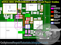
Now, the Nokia 5800 xpressmusic schematic diagram shown below an audio circuit which is feed from a the audio codec IC (not shown on the picture) Unlike most Nokia Audio circuits in some models, the 5800 xpressmusic has an audio amplifier chips or IC that amplifies the audio signal before it goes through the IHF ( Intermediate High Frequency) Speaker. This chip also designed to controls the audio signal's volume. It has two channels, the left and right channel, which  is so-called stereo type amplifier.
nokia 5800 audio circuit schematic diagram

The components layout and connection path lines with each certain components from the schematic diagram is in the picture below. The chips layout which I in-lined with colors indicates each certain components that are being shown or listed from the schematic diagram in the above image.
You can use this image to trace lines and faulty components by referring each component's desired values from an aide of schematic diagram above..  
nokia 5800 xpressmusic audio speaker ways
The complete connection tracks is shown below for complete troubleshooting guide.
Here's a simple tricks on how to troubleshoot with an aide of the picture below.

nokia 5800 xpressmusic ringtone speaker repair solution

Assuming that we already restore or flash it with its original or desired flash firmware and been already test the speaker working fine, but the problem still exist,
follow this some steps:
1. Determine which channel or speaker got no sound output. the left channel is where I colored "pink" and the right channel is colored "red". if both channel speaker got no sounds output, preferably the problem lies from the audio codec chip or from the audio amplifier  chip, but don't rush on there that quickly, it's unsure yet and ain't that easy to determine which one causes the problem. Always start from outer layer of the whole circuit,
what I mean is that check all components from the outside most components before going deep to the inner parts.

2. Check the following output filter coils, the value of this said coils are too small enough and quite possible easy to break and typically designed for the speakers protection. Replace if found busted.
3. Check and test the two other output filter coils in each designated lines. Replace if busted.
4. Check or rather replace the inputs capacitors on each channel, or by only which channel have a problem.
5. In this stage considering that all of the above is already done and those components were all fine and stable. this where we suspect the audio codec chip or the audio amplifier chip causes the problem.

The audio amplifier chip will take to test  first for it is an outer components rather than the audio codec chip.
6. Reheat or rework the chips or replace if possible that is the quickest method.
  BUT BEFORE THAT, in working on Integrated Circuit or chip, always check first if there is a voltage supply on it and or properly connected to ground lines. In this manner you are checking and testing the chip's itself, ob-course chips won't work without a proper power supply on it.
By an aide of the picture above trace the power supply voltage of the chip, it is range around 3.7 VDC which directly a voltage from the phone's battery.
8. The last stage is working on the Audio codec chip, in this stage needs extra care for an audio codec circuit is also combined with power management circuit. This what called the power IC.
Reheat, rework or reball it, is the last stage of whole troubleshooting procedure.

Nokia 5800 Xpressmusic Charger Not Supported Repair Solution

Nokia 5800 Xpressmusic Charger not supported repair guide
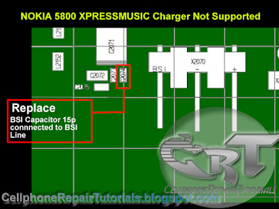
 The picture below shows the location of BTEMP thermistor which valued 47Kohms and connected to the BSI (battery size indicator) of a battery connector pin, this component holds the battery indication during charging operation process. Once this said thermistor become unstable or faulty, it will result to charger not supported shown on a LCD display  screen. The only solution is to replace this component with the same value as indicated.


The BSI capacitor which is located near to the battery BSI connector may cause the problem if  faulty or unstable. Replacement is also necessary.

If problem still exist after replacing this parts a deep troubleshooting analysis is required, The first step is to reflow or rework the integrated circuit (IC)chips which is where the charging circuits lines connected across to it.

Nokia 5800 XpressMusic Unlocked Phone with U.S. 3G, GPS with Free Voice Navigation, Wi-Fi, and 8 GB MicroSD Card--U.S. Version with Warranty (Black)

Nokia 5800 XpressMusic Not Charging Repair Guide

This is a step by step procedure on how to fix Nokia 5800 xpressmusic not charging problem issues.
1. Use and try different charger, a good and working one, may help undentify if the charger is working
    perfectly or not, check the charger voltage if there is a voltage flow across to it.
2. Replace a good and working Battery, a weak battery voltage may also occurs not charging issues, you
   can  also check and test the desired battery voltage.
3. if the problem still exist, Disassemble the handset.
4. Check the charging connector pin. make sure if it is clean, free from molds or corrosion and in properly
    allignment to the PCB  contact pads. replace if found damaged.
5. Trace the charging voltage path lines and components using the picture guides below.
    A. Check the Charger Voltage Line Paths
.   B. Check all Charging Components and replace if found busted or faulty.
Nokia 5800 XpressMusic Not Charging Repair picture Guide
     NOKIA 5800 Xpressmusic PCB layout of charging components


For beginners  tutorials on how to trace charging line paths link below:
How to Troubleshoot Not Charging Issues